
Lamda Components Pvt. Ltd. is a Bangalore-based manufacturer and exporter established in 1987, specializing in aluminum die casting, precision machining, die making, and precision steel parts for OEM and industrial customers. If you are asking "Can this machine run my part, and what do I need to send to confirm it?", this guide walks through the four factors that actually drive machine selection - tonnage, platen size, tie bar spacing, and weight limits - and what to submit for a fast feasibility review.
Machine selection is driven by projected area, gross shot weight, die envelope, and alloy - not part weight alone. Match those part inputs to the machine's clamping force, platen size, tie bar spacing, and casting capacity. Two parts of identical net weight can require different machines once cavity layout, runners, and alloy are considered.
Key takeaways
- Machine selection is driven by projected area, gross shot weight, die envelope, and alloy - not part weight alone.
- Clamping force (tonnage) must clamping force resists metal pressure across the part's projected area to help prevent flash and dimensional issues.
- Platen size and tie bar spacing are different checks - a die can fit the platen and still fail tie-bar clearance.
- Gross shot weight includes runners, biscuit, and overflows, not just the finished casting.
- Lamda operates cold-chamber aluminum pressure die casting machines in the 250T to 420T range, supported by in-house die making, machining, resin impregnation, leak testing, and CMM inspection.
- Send 2D/3D drawings, alloy, annual quantity, and quality requirements for a fast feasibility review.
How do you match a part to the right die casting machine?
Match the part's projected area, gross shot weight, die envelope, alloy, and cavity layout against the machine's clamping force, platen size, tie bar spacing, and casting capacity. Part weight alone does not confirm production feasibility, because the metal charge and die footprint per cycle can vary widely for parts of similar weight.
This is a production-feasibility decision, not a catalog lookup. Cavity count and runner design change the real machine load, so the machine choice stays provisional until the die layout is frozen.
Why part weight alone does not determine machine selection
The finished casting is only one part of what the machine sees each cycle. The machine must handle the full metal charge, and it must generate enough clamping force to keep the die closed against that charge across its entire projected area. Net part weight tells you neither of those things on its own.
Machine sizing involves several checks beyond the part itself:
- Runner system - the channels that feed molten metal from the shot sleeve into the cavity add measurable metal volume.
- Biscuit - the metal slug left in the shot sleeve at the end of injection.
- Overflow design - overflow wells and vents that capture cold metal and gas add both weight and projected area.
- Capacity margin - engineers normally keep margin above the estimated gross shot weight for stable filling and process consistency.
Engineer's note: Part weight alone is not enough. Runner, biscuit, overflow, and cavity layout can materially change required shot capacity and required tonnage - often adding a substantial share of the total metal per shot.
What is included in gross shot weight?
Gross shot weight is the full metal charge injected in one cycle: the net casting (cavity) weight plus runner weight, plus biscuit weight, plus any overflow metal. Machine shot-capacity checks must use this gross figure, not the finished part weight, because runners and biscuit often add a significant volume of metal per shot.
What machine limits matter most in die casting?
Five machine limits decide whether a part is feasible on a given machine: clamping force, platen size, tie bar spacing, shot weight and casting capacity, and die height. Each is a separate check, and passing one does not guarantee the others.
Clamping force (tonnage)
Clamping force - also called locking force or tonnage - is the force that keeps the die halves closed during metal injection. It must exceed the opening force created by molten metal pressure at the parting line acting across the part's total projected area, with a safety margin. If tonnage is undersized, the die can separate at the parting line, causing flash, dimensional drift, and process instability. If it is heavily oversized, you pay for capacity you don't use and may run less efficiently. The goal is a machine whose rated clamping force comfortably resists the calculated opening force while leaving a sensible margin.
Platen size
Platen size is the usable die-mounting surface on the machine's fixed and moving platens. The die's external mold dimensions must sit within this surface with room for clamping, ejection, and cooling connections. A larger die footprint - driven by cavity count and runner layout - needs a larger platen. Checking platen area alone is not sufficient, because the die must also pass the separate tie bar clearance check described below.
Tie bar spacing
Tie bar spacing is the clearance between the machine's tie bars - the columns that carry clamping load. The die must physically pass between these bars during mounting. This is a distinct check from platen size.
Common mistake: A die may fit the platen surface but still fail tie-bar clearance. Always check both the platen dimensions and the tie bar spacing together before confirming a machine.
Shot weight and casting capacity
Casting capacity is the maximum metal charge a machine can inject reliably per cycle. Your gross shot weight - part plus runners, biscuit, and overflows - must fall within this limit with margin. If the shot weight approaches the machine's ceiling, fill consistency and quality can suffer, so shot capacity is checked against the gross figure, never the net part weight.
Die height and mold dimensions
Every machine has a minimum and maximum die height (daylight) window. The closed die stack must fit inside that window so the machine can clamp fully and open enough to eject the casting. Overall mold dimensions, ejector layout, and any slides all factor into this fit check alongside platen and tie bar limits.
How projected area affects locking force
Molten metal inside the cavity pushes against the die faces with a pressure that depends on the alloy and process. The total projected area of the part, runners, gates, and overflows at the parting line determines how much opening force that pressure generates. Clamping force must be greater than this opening force, multiplied by a safety factor, to keep the die closed and prevent flash.
A practical estimation is:
F_clamp = P_injection × A_total × k
where A_total is the total projected area of all features at the parting line (part, runners, gates, overflows, and any slide or core faces), P_injection is the specific injection pressure for the alloy, and k is a safety factor typically in the 1.1–1.3 range depending on part complexity.
How is clamping force estimated from projected area?
Clamping force is estimated by first calculating the total projected area of everything inside the mold at the parting line - the part, runners, gates, and overflows - then multiplying by the injection pressure required for the alloy, and finally adding a safety margin. This ensures the die stays closed and resists flash throughout the shot.
How die size and cavity layout change machine choice
Die size is not the same as part size. A small part can require a large die once you add multiple cavities, a runner network, and overflow wells - and that larger die drives platen, tie bar, and die-height requirements upward.
Key layout effects on machine choice:
- Single-cavity vs multi-cavity: Adding cavities increases total projected area and gross shot weight, which can push the part into a higher-tonnage or larger-platen machine.
- Runner layout: Runner volume adds to shot weight, and runner projected area adds to the total area used in the clamping-force calculation.
- Overflow design: Overflows increase both metal volume and projected area, raising shot-capacity and tonnage margins.
- Die footprint vs part footprint: The die envelope, not the part outline, must pass the platen and tie bar checks.
Because these choices directly change projected area and shot weight, machine selection should remain provisional until cavity count and runner design are finalized.
Aluminum vs zinc die casting considerations
Alloy choice affects the process type, injection pressure, and therefore machine selection - even for parts of similar size. Zinc die casting typically runs on hot-chamber machines for zinc casting, where the injection system sits in the molten metal, enabling fast cycles and strong economics for small, precise, thin-walled parts. Aluminum die casting typically runs on cold-chamber die casting process machines, where metal is metered into a shot sleeve each cycle; this suits larger structural parts and higher-temperature service environments where weight and strength matter.
These differences influence machine type, injection pressure, cycle-time expectations, and economic fit. Lamda specializes in aluminum pressure die casting on cold-chamber HPDC machines, supported by in-house die making and full downstream finishing.
Machine selection reference tables
Use these tables to see which part inputs drive which machine specs, how each machine parameter behaves when mis-sized, and what data must be locked before a machine is confirmed.
Table 1 - Machine selection inputs
| Input factor | What it measures | Why it matters | Affects machine spec |
| Part weight | Net finished casting mass | Starting point for shot weight | Drives shot-capacity sizing |
| Projected area | 2D area at the parting line | Sets opening force | Drives clamping force (tonnage) |
| Alloy type | Metal grade and process | Sets injection pressure and process | Drives tonnage and hot/cold chamber choice |
| Die size | External mold dimensions | Physical fit | Determines platen, tie bar, die height |
| Runner system | Feed channel volume/area | Adds metal and area | Increases shot weight and tonnage |
| Overflow design | Overflow volume/area | Adds metal and area | Increases shot capacity and tonnage margin |
| Cavity count | Parts per shot | Multiplies area and metal | Can force higher tonnage or larger platen |
| Trim requirements | Secondary trim tooling | Trim strategy and ejection | Influences tooling envelope and machine fit |
Table 2 - Machine parameter vs selection decision
| Machine parameter | What to check | Risk if undersized | Risk if oversized |
| Clamping force | Exceeds opening force + margin | Flash, dimensional drift, instability | Higher cost, less efficient run |
| Platen size | Die footprint fits surface | Die won't mount | Underused capacity |
| Tie bar spacing | Die passes between bars | Die can't be loaded | Larger machine than needed |
| Shot weight | Gross charge within capacity | Incomplete fill, defects | Wasted capacity |
| Die height | Closed stack within daylight | Cannot clamp or eject | Setup inefficiency |
| Ejector layout | Ejection aligns with die | Ejection issues, damage | Rework of die interface |
Table 3 - Part-to-machine feasibility checklist
| Checkpoint | Data needed | Who validates |
| Projected area known? | Part + runner + overflow area | Tooling/process engineer |
| Gross shot weight estimated? | Part + runner + biscuit + overflow | Process engineer |
| Die envelope defined? | Mold dimensions, die height | Tooling engineer |
| Alloy confirmed? | Grade and specification | Buyer + engineering |
| Cavity count fixed? | Layout and volume plan | Tooling + program team |
| Trim die considered? | Trim strategy, secondary ops | Tooling engineer |
Common part-to-machine matching mistakes
Most machine-fit problems trace back to a small set of avoidable errors. Screening for these early prevents bad RFQs and wasted quoting cycles.
- Assuming part weight is enough. Net weight ignores runners, biscuit, overflows, and projected area - all of which drive the real machine load.
- Ignoring tie-bar clearance. A die that fits the platen can still fail to pass between the tie bars.
- Forgetting trim die and secondary operations. Trim strategy and downstream machining can affect tooling layout and machine fit.
- Confirming the machine too early. Locking a machine before die layout is frozen invites rework when cavity count or runners change.
- Overlooking cavity layout impact. Cavity count multiplies projected area and shot weight, sometimes pushing the part to a larger machine.
When to ask for supplier review: If projected area, cavity count, or runner design are still changing, machine selection should remain provisional. Bring in your supplier's tooling and process team before freezing the machine.
What to send Lamda for a fast feasibility review
Sending the right data upfront reduces RFQ back-and-forth and speeds a production-feasibility answer. The more complete your package, the faster Lamda's engineering team can confirm fit and quote.
Include the following:
- 2D drawing with GD&T dimensioning and tolerancing and/or 3D CAD file (STEP/IGES)
- Alloy specification or target properties (for example ADC12, A380 aluminum casting alloy properties, LM6)
- Estimated annual volume and call-off pattern, plus lifetime volume where relevant
- Minimum order quantity (MOQ)
- Estimated net part weight and target shot weight, if available
- Critical-to-quality dimensions, tolerances, and datum scheme
- Surface finish and coating requirements
- Machining scope and secondary operations
- Leak-test / pressure-tightness requirements (method, pressure, hold time)
- Testing, certification, and documentation expectations (PPAP production part approval process, ISIR, RoHS/REACH/IMDS)
- Packaging, labelling, delivery schedule, and export documentation needs
- Target SOP date and tooling lead-time expectations
Send your RFQ to sales@lamdacomponents.com with 2D and 3D drawings, annual quantity, MOQ, and complete quality requirements. Contact us to start a feasibility review.
About Lamda Components Pvt. Ltd.
Lamda Components Pvt. Ltd. is a Bangalore-based manufacturer and exporter established in 1987, serving OEM and industrial customers in domestic and international markets with end-to-end aluminum die casting and precision machining.
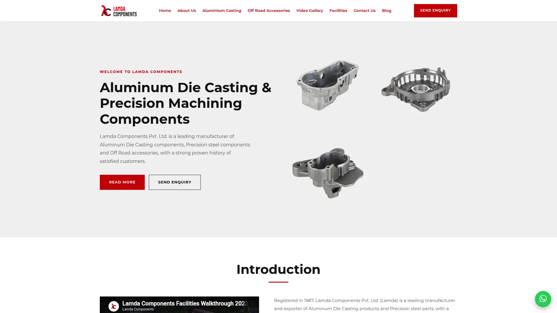
Capabilities include:
- Aluminum pressure die casting on cold-chamber machines in the 250T to 420T range, with auto ladle, auto spray, and auto extractor
- In-house die making and tool design
- Precision machining, shot blasting, vibro deburring, resin impregnation for porosity sealing, leak testing, powder coating/painting, and sub-assemblies
- CMM inspection and quality validation
- Precision steel parts and off-road vehicle accessories
Lamda operates under ISO 9001 quality management, IATF 16949 automotive quality standard (IATF 16949:2016), and ISO 14001:2015 environmental management certification for relevant operations. Sectors served include automotive driveline and electrical systems, EV motors, fuel injection pumps, alternators and starter motors, hydraulic and pneumatic equipment, white goods and electrical appliances, industrial housings and enclosures, and selected medical and industrial applications.
Contact: Lamda Components Pvt. Ltd. Plot No.30, Veerasandra Industrial Area, Bangalore – 560 100, Karnataka, India Phone: +91 76193 11331 Email: sales@lamdacomponents.com
Learn more via About Us, Facilities, and Products / Capabilities, or Contact us to begin.
Frequently asked questions
How do you choose the right die casting machine for a part?
Match the part's projected area, gross shot weight, die envelope, alloy, and cavity layout to the machine's clamping force, platen size, tie bar spacing, and casting capacity. Part weight alone does not confirm production feasibility, because metal charge and die footprint vary between parts of similar weight.
What is die casting machine tonnage?
Tonnage is the clamping force that keeps the die closed during metal injection. It must resist metal pressure across the part's projected area, with a safety margin, to avoid flash, process instability, or dimensional issues during casting.
What is the difference between platen size and tie bar spacing?
Platen size is the usable die-mounting surface, while tie bar spacing is the clearance between the machine's tie bars. A die may fit the platen but still fail tie-bar clearance, so both checks must be confirmed together.
Why is shot weight different from part weight?
Part weight is only the finished casting. Shot weight is the full metal charge per cycle, including runners, biscuit, and overflows. Machine selection must consider gross shot weight, not just net part weight, because runners and biscuit add substantial metal.
Can two parts with the same weight need different machines?
Yes. Differences in projected area, cavity count, runner design, overflow design, and alloy can change clamping force and shot-capacity requirements, so two parts of equal net weight can require different machines.
What machine range can Lamda Components run?
Lamda operates cold-chamber aluminum pressure die casting machines in the 250T to 420T range, supported by in-house die making, machining, resin impregnation, leak testing, and CMM inspection. Send your drawing, alloy, and volume for a fast feasibility review.
When should die casting machine selection be finalized?
Machine selection should stay provisional until die layout, cavity count, and runner design are confirmed, since these directly affect projected area, gross shot weight, and required clamping force.